IPv4 Service IP implementation details
8 minute read
In this wiki page, we’ll go through the details of the IPv4 implementation of the Service IPs in Oakestra.
The building blocks are:
- Network Overlays
- Proxy Translation
- Interest registration
Network Overlays
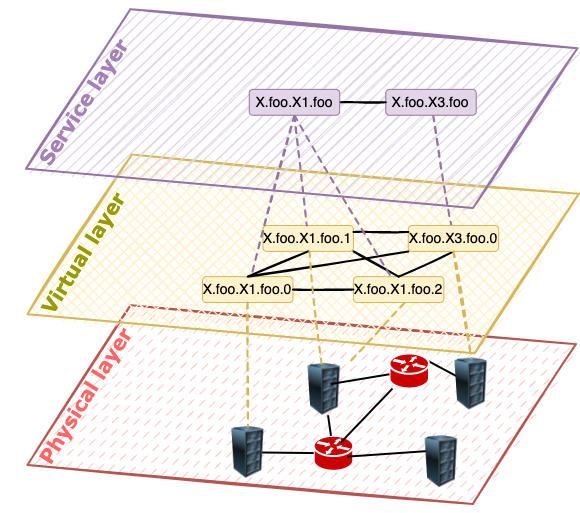
The abstraction required to enable service-to-service communication spans 3 different layers.
Physical layer
At the very bottom of the hierarchy, we have the physical layer, where we address machines rather than microservices or containers. In this space, an IP address is an address that can be used to uniquely identify a machine and reach it. In Oakestra, we keep track of this layer, pairing each service with a Node IP and Port. The pair IP:port enables us to reach multiple devices sharing the same IP address (NAT). Each worker node exposes the network stack required to enable the upper layers of the overlay at the assigned port.
Virtual layer
Each physical machine is provisioned with a virtual subnetwork. The subnetwork is assigned by the root orchestrator. When instantiating a container, the system provides a so-called Namespace IP, which is an IPv4 address provisioned from the virtual subnetwork of the node. This address is used to route the traffic within the platform to the running containers. The current implementation uses a default fixed netmask of 26 bits for the node subnetwork from the private 10.18.0.0/16 network, allowing over 1024 devices, each supporting 64 containers, for a maximum of 65536 containers. Support for more devices and bigger subnetworks can be achieved by changing the default subnetwork to, i.e., 10.0.0.0/8 or even further transitioning to virtual IPv6 networking.
Service layer
This is the layer where we abstract from the virtualization technology in use to a Service. The service layer does not take into consideration the physical positioning of services, the number of instances of each service, the subnetworks, or the routing. This layer provides abstractions that allow the developers to forget about the underlying implementation and just address the service required for the business logic of the application. This abstraction is enabled by the Service IPs. These are a set of IPv4 addresses that identify services and all their instances and that can be used to transparently pick the right instance and establish a connection. A Service IP expresses an inherent balancing policy, and, for each service, we have as many Service IPs as the implemented system balancing policies (Look at the Semantic Addressing page of this wiki for more details).
A subset of the Service IPs are the Instance IPs. They balance the traffic always to a specific instance of a service. Therefore, when deploying a service, the system will provision the following addresses:
- 1 Load Balanced Service IP for each balancing policy implemented in the system
- 1 Instance IP for each new instance of the service that has been deployed.
The latest version of Oakestra (v0.4.201), only implements Round Robin Service IPs.
One might ask, what’s the difference between an Instance IP and a Namespace IP? They operate on 2 different abstraction layers. The Namespace IP depends on the virtualized subnetwork of a worker node and changes when migrating an application from one node to another. It cannot be provisioned beforehand and must not be used by developers. The Instance IP is part of the Service layer abstraction. Therefore it identifies an instance regardless of migration operations, scales up, scales down, and can be provisioned even before the deployment of a service instance.
Proxy Translation
The Service layer networking is achieved thanks to a worker-level tun-proxy transparently instantiated as part of the Oakestra network component. The following picture is an example of what happens in a worker node based on the IPv4 implementation of the NetManager component.
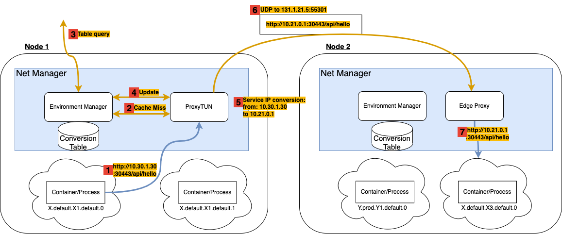
In this example, we have two worker nodes, namely Node 1 and Node 2, each containing two containers. The containers are instantiated and managed by the NodeEngine (See High-Level Architecture wiki), while the Net Manager, creates a network namespace for each container (the cloud surrounding the container), enabling the Virtual Layer abstraction.
The Service Layer abstraction is realized hierarchically with a mechanism of route Interest Registration and Proxying Translation. This section details the proxy Translation, hence the mechanism that allows transparent conversion of Service IPs into Namespace IPs, therefore transparent Virtual Layer - Service Layer conversion.
Following the example mentioned above, suppose we deployed services X1 and X3 using the following deployment descriptor.
{
  "sla_version" : "v2.0",
  "customerID" : "Admin",
  "applications" : [
    {
      "applicationID" : "",
      "application_name" : "X",
      "application_namespace" : "default",
      "application_desc" : "X application",
      "microservices" : [
        {
          "microserviceID": "",
          "microservice_name": "X1",
          "microservice_namespace": "default",
          "virtualization": "container",
          "code": "docker.io/X/X1",
          "addresses": {
            "rr_ip": "10.30.0.1"
          },
        },
        {
          "microserviceID": "",
          "microservice_name": "X3",
          "microservice_namespace": "default",
          "virtualization": "container",
          "code": "docker.io/X/X3",
          "addresses": {
            "rr_ip": "10.30.1.30"
          	},
        }
      ]
    }
  ]
}
Therefore we register into the platform two services, X.default.X1.default and X.default.X3.default. At deployment time, we request 2 instances of X1 (X.default.X1.default.0 and X.default.X1.default.1) and one instance of X3 (X.default.X3.default.0). The scheduling decision places the instances as shown in the picture.
From the deployment descriptor, we asked the platform to provision the Service IP 10.30.1.30 to X3 with Round Robin policy. Therefore, X1 will use this address to perform load-balanced requests toward X3.
1 http://10.30.1.30:30443/api/hello
X1 performs a GET request using the Service IP 10.30.1.30. The default getaway for the 10.0.0.0/8 subnetwork is the ProxyTUN component of the Net Manager. The request will be directed there.
From an L4 perspective, the packet will look somewhat like this:
from ip: 10.19.1.3
to ip: 10.30.1.30
from port: 34278
to port: 30443
payload: ....
The from ip, is the Virtual Layer IP, the Namespace IP of the container. This Namespace IP is assigned to the VETH device used to connect the container namespace to the virtual bridge in the system namespace.
2 Cache Miss
When receiving the request packet, the proxy does not yet have an active conversion entry in its cache. This results in a cache miss. With a cache miss, the proxy TUN fetches the information required for the conversion to the Environment Manager. This component keeps track of the services deployed internally in the worker node, as well as the relevant services deployed on other worker nodes.
This is an example of the Conversion Table maintained by the Environment Manager at this moment.
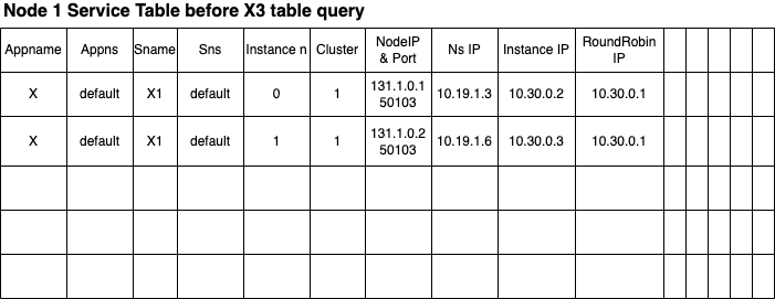
The entries of the table keep the cross-layer information of each service, including the physical layer address and port, the virtual layer address, and all the service layer addresses. As the number of records is limited, the table only keeps track of the services currently deployed in this machine. No interest in external services has been recorded so far.
3 Table query
When the address 10.30.1.30 must be converted using the Conversion Table, this will result in a table miss. The Environment Manager is then forced to ask the cluster orchestration for an entry that enables the conversion of this address.
This operation is called table query and serves a double purpose:
- Hierarchical lookup to fetch the required information.
- If the information exists, an interest in that information is registered. Therefore any update, such as a service migration or service scaling, results in an update for that table entry.
This is one of the building blocks of the proposed abstraction, and it is detailed in the Interest Registration section.
4 Update
Upon completion of the table query, the internal Conversion table is updated as follows.
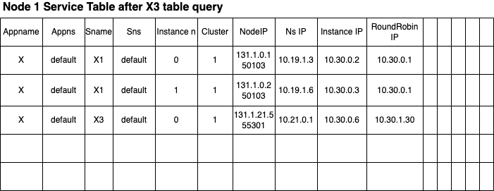
The cluster resolved the Service IP 10.30.1.30 into a table entry describing only X.default.X3.default.0 (apparently, no other instances are in the system yet).
The Environment Manager can now answer the proxy with the virtual layer and physical layer addresses resolving the previous cache miss and the balancing policy metadata associated with the address. In this case the response will look like this:
policy: Round Robin
instances: [
	{
		NS IP: 10.21.0.1
		Node IP: 131.1.21.5
		Node port: 55301
		Cluster: 1
		...
		...
	}
]
5 Service IP conversion: from: 10.30.1.30 to 10.21.0.1
Given the resolution details, the proxy, using the balancing policy information, picks an instance from the instance list and adds an entry to the conversion list.
In this example, the entry will look like this:
                FROM              TO
                __________________________________
matching rule:  10.19.1.3:34278 - 10.30.1.30:30443
convert to:     10.30.0.2:34278 - 10.21.0.1:30443
Notice how the proxy also replaces the from address with the Instance IP of X1.
In abstract terms, the proxy is converting a the incoming packet from the form of
{
	from:<Sender Virtual Layer Address>
	to:<Receiver Service Layer Address>
}
to
{
	from:<Sender Service Layer Address>
	to:<Receiver Virtual Layer Address>
}
The conversion just shown is the key to enabling transparent Service Layer abstraction.
6 UDP to 131.1.21.5:55301
In this step, we see how the ProxyTUN uses the Physical layer information to create a tunnel between Node 1 and Node 2 and forward the packet to the destination machine’s Net Manager.
7 http://10.21.0.1:30443/api/hello
The Net Manager does not need to translate the incoming packet as the recipient IP is a Virtual layer known address. Notice how a response from X3 to X1 follows the same steps shown in this example.
Interest Registration
Here we show a sequence diagram of how a table query and an interest registration work in the worker-cluster-root hierarchy.
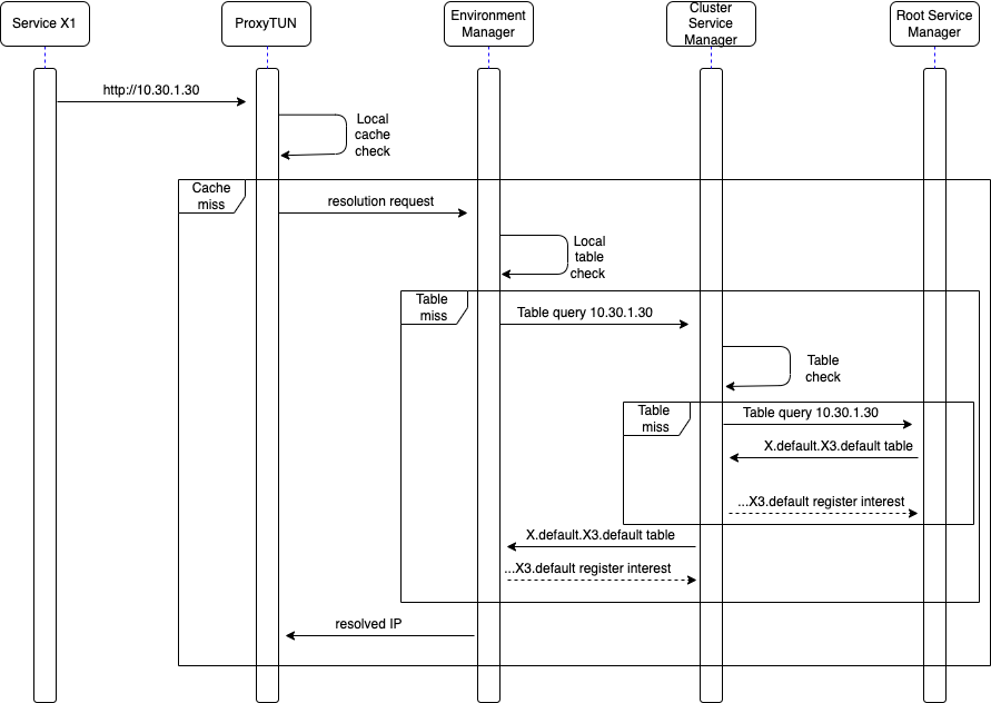
- The environment manager keeps the ‘interests subscriptions’ for 10 seconds. If the route is not used for more than 10 seconds, the interest is removed, and the table entry is cleared.
- A cluster maintains an interest as long as at least one worker node is interested in that route.
- A worker node is ALWAYS subscribed to interests regarding the instances deployed internally.